Frequently Asked Questions
Browse FAQ by Product
BAT R/T | BATCHtrol-2 | Intellect-69 | KEPtrol R/T | MINItrol | Squirt | SUPERtrol-1 | SUPERtrol-2
BAT R/T FAQ
For Pulse Inputs the Count K-Factor is equal to the number of pulses per unit of measure which is determined by the flowmeter. (This Information is typically on the flowmeter calibration sheet or stamped on the flowmeter itself).
The K-Factor is Calculated as follows:
Flow Total Indication = Sum of Input Pulses / (Factor x Factor Multiplier)
The Rate Time is menu selectable: You will have the option of choosing Seconds, Minutes or Hours which adds the appropriate multiplier into the equation. See Below.
Flow Rate Indication = (Input Frequency / (Factor x Factor Multiplier) x Time Scaler
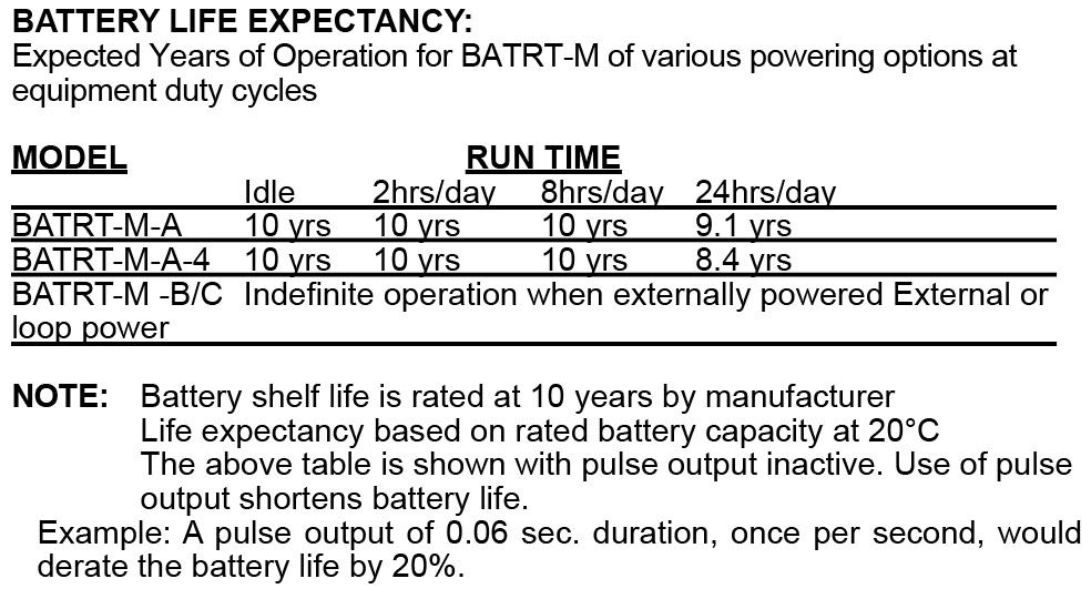
The Life Expectancy Table is listed below. |
The Factory back door code for the BATRT can be obtained by calling the factory or send an email.
The Operating Temperature of the BATR/T is listed below: OPERATING TEMPERATURE |
ACCURACY:
0.01% Reading, ±1 count
Temperature Drift: 50 ppm/°C Worst Case
Yes, the BATR/T front panel is NEMA 4X rated. This rating is also comparable to the European standard IP65.
| The user can view the Rate and Total of flow on the Two Line Display. The Rate is shown on the top line and the Total is shown on the bottom line of the display. |
The BATR/T has a battery backed memory and is capable of storing program and count data for the life of the battery. The unit also has a “BAT” warning that will activate on the display when the battery reaches the end of its useful life. |
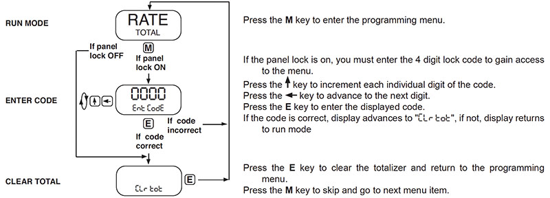
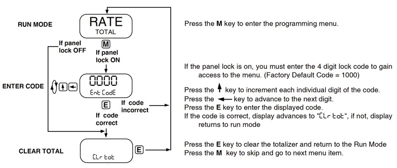
The flow total may be cleared by the front panel or by a contact closure on the remote reset terminal to circuit common. To reset the unit from the front panel, the following sequence is required:
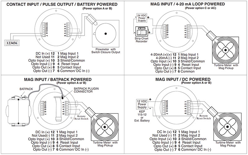
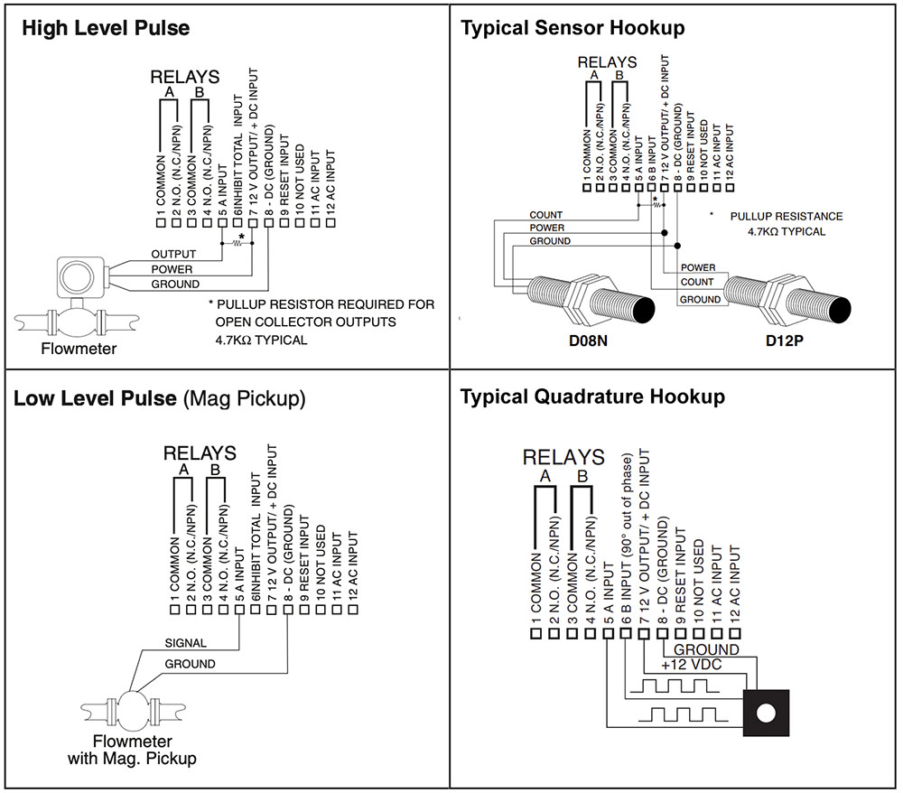
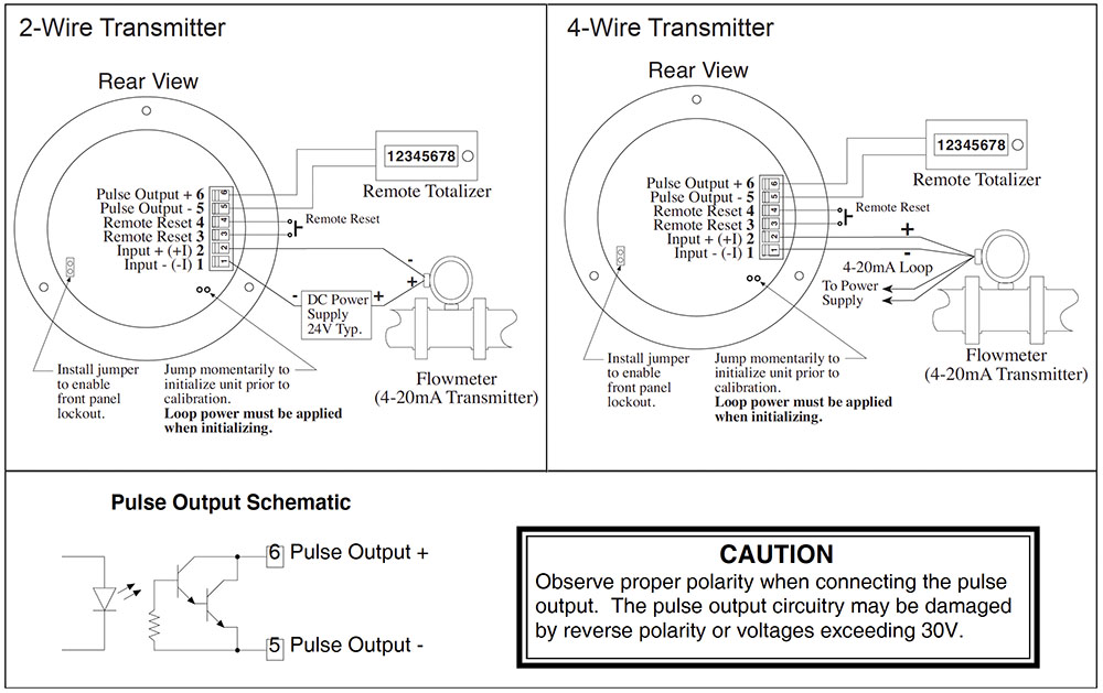
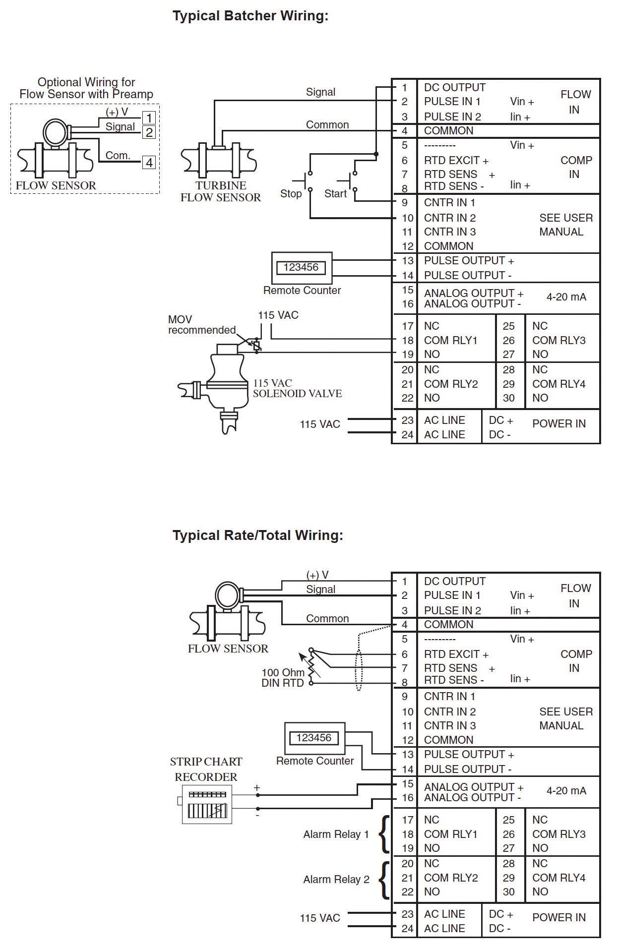
Below you will find typical wiring diagrams to help you wire a flowmeter to the BATR/T
BATCHtrol II (BT2) FAQ
For Pulse Inputs the Count K-Factor is equal to the number of pulses per unit of measure which is determined by the flowmeter. (This Information is typically on the flowmeter calibration sheet or stamped on the flowmeter itself).
The Rate K-Factor is calculated by dividing the Count K-Factor by the time conversion factor.
Example:
Count K-Factor = pulses per unit of measure (gallon, foot, revolution etc.…).
Rate K-Factor (rate per second) = pulses per unit / 1
Rate K-Factor (rate per minute) = pulses per unit / 60
Rate K-Factor (rate per hour) = pulses per unit /3600
Rate K- Factor: 10000/R, where R = high output rating (20mA or 5V) of transmitter. 10000 divided by 20mA or 5V rating of transmitter. Eg. 20mA rating of transmitter is 1500 gal. per min. The rate K – Factor to key into the unit for gal. per min. is 6.6666667 (10000 divided by 1500). The Count K-Factor can be calculated by modifying the Rate K-Factor to reflect the rate in units per second. If the Rate is set for rate per minute, multiply the Rate K-Factor by 60; if rate per hour, multiply the rate K-Factor by 3600. Counter K-Factor: = 6.6666667 x 60 = 400 |
The Factory back door code for the BATCHtrol II can be obtained by calling the factory or send an email.
Terminal 5 (Stop/Reset Input) has two functions. When activated during a batch, the unit will STOP. When the unit is STOPPED or after a batch is complete, activating this input will reset the Batch Total. If terminal 5 is held high (4-30Vdc), all start inputs will be inhibited. Wiring a push button switch between Terminal 13 and Terminal 5 will accomplish these functions.
Preset and Prewarn activate the Preset Relay and the Prewarn Relay at a given Batch amount. When entering a value into either one of these setpoints it will cause the corresponding relay to change state at that batch amount. When the start button is pushed, the two relays engage simultaneously to start flow. When the prewarn number is reached, one relay drops out. When the preset number is reached, the other relay drops out. The user may enter the two numbers when setting up the batch counter. The prewarn is set a certain number of counts less than the preset number. If the prewarn is set larger than the preset, the message “PREWRONG” will appear on the disp |
Yes, the BATCHtrol II front panel is NEMA 4X rated. This rating is also comparable to the European standard IP65. |
The user can view the Rate, Total and Preset Number by toggling between the three displays with the Rate/Total button on the front of the unit. The user can also view the Grand Total by pushing the “Enter” button once while viewing the Total. The Grand Total will be the flashing Totalizer. Pushing the “Enter” button again will return you to the Total
The Batchtrol II has EEPROM memory and is capable of storing program and count data for a minimum of 10 years. This is also referred to as non-volatile memory
There are two DC outputs available when the unit is powered with AC Voltage. The D.C. outputs are rated at 100ma maximum current draw
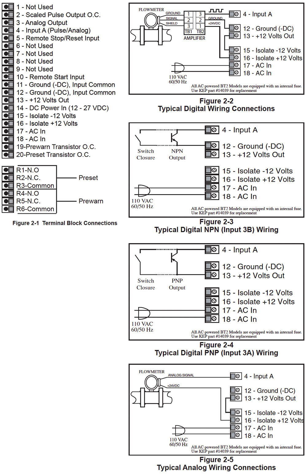
Below you will find typical wiring diagrams to help you wire a flowmeter to the BATCHtroll II
Intellect-69 (INT69) FAQ
The Factory back door code for the INT68 can be obtained by calling the factory or send an email.
There are several reasons this could be happening. Please check the following: Analog or Voltage loop broken. Check connections to make sure signal is getting to the unit. |
There are several reasons this could be happening. Please check the following: Make sure the input selection is selected for the correct input (4-20mA, 0-20mA, 0 –10vdc, 1-5vdc) |
There are several reasons this could be happening. Please check the following: Make sure the presets are not set at zero |
There are several reasons this could be happening. Please check the following:
The “set low” is set at a value other then zero.
The input has a value higher then 4mA on it. ¾
Make sure the input selection is selected for the correct input (4-20mA, 0-20mA, 0 –10vdc, 1-5vdc)
| When the Relays are assigned to total and there is a duration set other than zero, the totallizer will count up to the preset value then the relay will close for the set duration of time and the totalizer will aut-reset to zero. If this is not the desired operation enter the programming menu and under relays in the program change the “dur” (duration) to .00 or change the relays to follow the rate display. |
Please try the following:
Make sure that the analog out option was ordered (check the model number to see if this option is specified)
The Analog Output is a sinking output and must be looped to a power source that is not common with the INT69. Preferably out of terminal 7 through meter and back to terminal 2.
The user can view the Rate ,Total , Peak and Vally of flow by pressing the view button on the front of the unit. The Peak is the highest value the display has read and the vally is the lowest value. |
The Intellect-69 has EEPROM memory and is capable of storing program and count data for a minimum of 10 years. This is also referred to as non-volatile memory
The DC output isavalable when the unit is powered with AC Voltage. The D.C. output is rated at 50ma maximum current draw.
Yes, you can set the Set Hi at a low value and the Set Lo at a High value.
This is also true for the Analog out put as well.
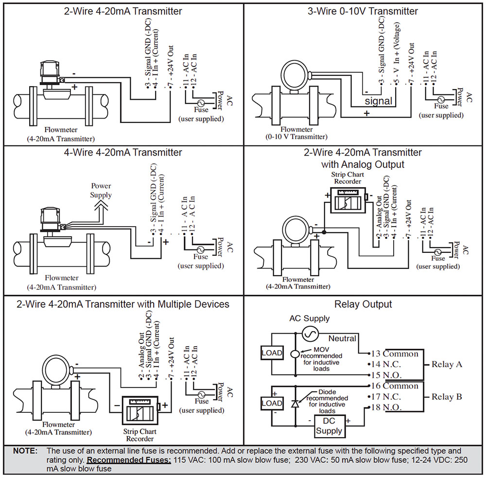
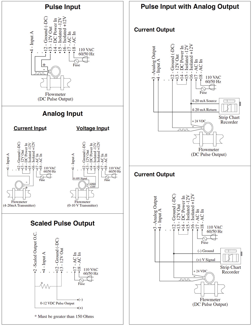
Below you will find typical wiring diagrams to help you connect a flowmeter:
KEPtrol R/T (KRT) FAQ
For Pulse Inputs the Count K-Factor is equal to the number of pulses per unit of measure which is determined by the flowmeter. (This Information is typically on the flowmeter calibration sheet or stamped on the flowmeter itself). The Rate K-Factor is calculated by dividing the Count K-Factor by the time conversion factor. Example: Rate K-Factor (rate per second) = pulses per unit / 1 |
Rate K- Factor: 10000/R, where R = high output rating (20mA or 5V) of transmitter. 10000 divided by 20mA or 5V rating of transmitter. Eg. 20mA rating of transmitter is 1500 gal. per min. The rate K – Factor to key into the unit for gal. per min. is 6.6666667 (10000 divided by 1500). The Count K-Factor can be calculated by modifying the Rate K-Factor to reflect the rate in units per second. If the Rate is set for rate per minute, multiply the Rate K-Factor by 60; if rate per hour, multiply the rate K-Factor by 3600. Counter K-Factor: = 6.6666667 x 60 = 400 |
The Factory back door code for the KEPtrol R/T can be obtained by calling the factory or send an email.
Wiring a switch between Terminal 13 and Terminal 5 can remotely reset the unit. The Remote Reset is positive edge triggered; once it is reset by a 3 -30Vdc signal the unit will reset. If the reset is then held high the unit will continue to count until the signal is removed and applied again |
Preset A and Preset B activate Relay A and Relay B at a given setpoint. When entering a value into either one of these Presets it will cause the corresponding relay to change state at that setpoint. The Relays can also be programmed to follow Rate or Total.
Yes, the KEPtrol R/T front panel is NEMA 4X rated. This rating is also comparable to the European standard IP65.
The user can view the Rate and Total of flow by toggling between the two displays with the Rate/Total button on the front of the unit. The user can also view the Grand Total by pushing the “Enter” button once while viewing the Total. The Grand Total will be the flashing Totalizer. Pushing the “Enter” button again will return you to the Total.
The KEPtrol R/T has EEPROM memory and is capable of storing program and count data for a minimum of 10 years. This is also referred to as non-volatile memory
There are two DC outputs available when the unit is powered with AC Voltage. The D.C. outputs are rated at 100ma maximum current draw
Below you will find typical wiring diagrams to help you wire a flowmeter to the KEPtrol R/T
MINItrol (MRT) FAQ
The Factory back door code for the MRT can be obtained by calling the factory or send an email.
There are several reasons this could be happening. Please check the following: Check connections to make sure input signal is getting to the unit. You can test the inputs by jumping terminal 7 12vdc output to the inputs. Make sure the Factor is set for one when testing this way. ¾ |
The most frequent reason is that the Scaling Factors are set to the wrong values. Check that the Factors are set to the proper values for the sensor you are connecting. |
There are several reasons this could be happening. Please check the following:
The unit is trying to display a value that is too large for the display. Check the decimal point location under count in the program.
The Factor value is to small
This will happen often with the Mag input option. Make sure customer is using shielded cable and it is grounded propperly. |
When the Relays are assigned to total and there is a duration set other than zero, the totallizer will count up to the preset value then the relay will close for the set duration of time and the totalizer will aut-reset to zero.
If this is not the desired operation enter the programming menu and under relays in the program change the “dur” (duration) to .00 or change the relays to follow the rate display.
Please try the following:
Make sure that the analog out option was ordered (check the model number to see if this option is specified)
The Analog Output is a sinking output and must be looped to a power source that is not common with the INT69. Preferably out of terminal 7 through meter and back to terminal 2.
Make sure the set Hi and set Lo are not both at zero.
The user can view the Rate of the A input and the Total of both A & B by pressing the view button on the front of the unit. The B Total is the display with all the decimals in it. |
The MINItrol has EEPROM memory and is capable of storing program and count data for a minimum of 10 years. This is also referred to as non-volatile memory
The DC output is available when the unit is powered with AC Voltage. The D.C. output is rated at 50ma maximum current draw. |
There are two separate dividing scale Factors that are entered as the number of pulses per desired unit of measurement.
Example: 50 pulses equal 10 pound of fluid. To display in pounds your Factor would be 5. (50 pulses / 10 pounds)
Below you will find typical wiring diagrams to help you connect a flowmeter or other sensor:
Squirt FAQ
The 4-20mA current span is the span you expect the SQUIRT to interpolate between. The Squirt is scaled by assigning a “Low Range” and a “High Range” to the Analog Low and High inputs. Let’s say that the sensor gives off an output of 4mA (milliamps) when it measures “0” gallons and 20mA when it measures “10” gallons. Through the keyboard you dial in “0” for 4mA (Rate Low), and “10.00” for 20mA (Rate High) and you have completed scaling the unit. Typically the customer will tell you the range they would like to use for their application.
The battery standby life expectancy on the SQUIRT is 2 years. The battery type is: 3V 250mA-H Lithium (2yr. Standby life).
The Factory back door code for the BATRT can be obtained by calling the factory or send an email.
The Operating Temperature of the SQUIRT is listed below:
OPERATING TEMPERATURE
-4°F (-20°C) to + 158°F (70°C)
Extended Temp: -22°F (-30°C) to + 158°F (70°C)
ACCURACY: (Rate @ 20°C)
0.1% Full Scale Resolution, ±1 count
Temperature Drift: 50 ppm/°C Typical 200 ppm/°C Worst Case
Yes, the SQUIRT front panel is NEMA 4X rated. This rating is also comparable to the European standard IP65.
The Display flashes when the Pulse output is exceeded. When the output is exceeded the data from the pulse output is then unreliable. If the customer is not using this feature it can be turned off. If the customer needs the output he/she will have to set the pulse output divider to a higher value.
The SQUIRT has a battery backed memory and is capable of storing program and count data for the life of the battery. The unit also has a “BAT” warning that will activate on the display when the battery reaches the end of its useful life. |
The flow total may be cleared by the front panel or by a contact closure on the remote reset terminals 3 and 4. To reset the unit from the front panel, the following sequence is required:
Below you will find typical wiring diagrams to help you wire a flowmeter to the SQUIRT
SUPERtrol-1 (ST1) FAQ
For Pulse Inputs the Count K-Factor is equal to the number of pulses per unit of measure which is determined by the flowmeter. (This Information is typically on the flowmeter calibration sheet or stamped on the flowmeter itself).
The Rate Time is menu selectable it can be found in the “Setup Indicators Menu” under “Rate”. You will have the option of choosing Seconds, Minutes, Hours or Day which adds the appropriate multiplier into the equation.
The 4-20mA current span is the span you expect the Supertrol-1 to interpolate between. The Supertrol-1 is scaled by assigning a “Low Range” and a “High Range” to the analog Low and High inputs of the Flow Input Menu. Let’s say that the sensor has an output of 4mA (milliamps) when it measures “0” GPM and 20mA when it measures “10” GPM. Through the keyboard you enter in “0” for 4mA (Rate Low), and “10” for 20mA (Rate High) and you have completed scaling the unit. Typically the customer will tell you the range they would like to use for their application.
The unit is shipped from the Factory with an Operator Password of “0” and a Supervisor Password of “2000” these should be tried first before giving the customer the back door code. The Factory back door code can be obtained by calling the factory or send an email.
Yes. The analog output is Isolated. Below you will find the specifications for the analog output that customers usually ask about.
The Analog Output is: Isolated Current Sourcing, Isolated I/P/C: 500 V
The Available Ranges are: 4-20 mA, 0-20 mA
The Resolution is: 12 bit
The Accuracy is : 0.05% FS at 20 Degrees C
The Update Rate is: 1 update/sec minimum
The Temperature Drift is: Less than 200 ppm/C The Maximum Load is: 1000 ohms (at nominal line voltage)
Yes. The Supertrol-1 is equipped with a battery backed real time clock that displays time and date. The format is: 12 or 24 hour time display and Day, Month, Year date display. |
Yes, the front panel is NEMA 4X rated. This rating is also comparable to the European standard IP65.
The user can view the Rate and Total of flow as well as the Grand Total, Temperature, Density, Time, Date, Preset 1 and Preset 2. This can be accomplished by pushing the appropriate button on the front of the unit or by setting up the Scroll List to display the the information desired through a scrolling display
The Supertrol-1 has the following Listings: “CE” which is the European noise immunity Standard, and |
The D.C. output is rated at 100ma maximum current draw. The D.C. output is also selectable. The user can select from three excitation voltages of 5, 12 or 24 Vdc to power their transmitters
Below you will find typical wiring diagrams to help you wire a flowmeter to the Supertrol-1
SUPERtrol-2 (ST2) FAQ
For Pulse Inputs the Count K-Factor is equal to the number of pulses per unit of measure which is determined by the flowmeter. (This Information is typically on the flowmeter calibration sheet or stamped on the flowmeter itself).
The Rate Time is menu selectable it can be found in the “Setup Indicators Menu” under “Rate”. You will have the option of choosing Seconds, Minutes, Hours or Day which adds the appropriate multiplier into the equation.
The 4-20mA current span is the span you expect the Supertrol-2 to interpolate between. The Supertrol-2 is scaled by assigning a “Low Range” and a “High Range” to the analogous Low and High inputs of the Flow Input Menu. Let’s say that the sensor gives off an output of 4mA (milliamps) when it measures “0” ACFM and 20mA when it measures “10” ACFM. Through the keyboard you dial in “0” for 4mA (Rate Low), and “10” for 20mA (Rate High) and you have completed scaling the unit. Typically the customer will tell you the range they would like to use for their application.
The unit is shipped from the Factory with an Operator Password of “0” and a Supervisor Password of “2000” these should be tried first before giving the customer the back door code. The Factory back door code can be obtained by calling the factory or send an email.
Yes. The analog outputs are Isolated. Below you will find the specifications for the analog outputs that customers usually ask about.
The Number of Outputs are: 2
The Analog Output Type is: Isolated Current Sourcing (shared common)
Isolated I/P/C: 500 V
The Available Ranges are: 0-20 mA, 4-20 mA (menu selectable)
The Resolution is: 16 bit
The Accuracy is: 0.05% FS at 20 Degrees C
The Update Rate is: 5 updates/sec
The Temperature Drift is: Less than 200 ppm/C
The Maximum Load is: 1000 ohms
Yes. The Supertrol-2 is equipped with either a super cap or a battery backed real time clock that displays time and date. The format is: 24 hour time display and Day, Month, Year date display. (Daylight savings time is optional). |
Yes, the front panel is NEMA 4X rated. This rating is also comparable to the European standard IP65.
The user can view the Rate and Total of flow as well as the Grand Total, Temperature, Pressure, Density, Time, Date, Alarm 1 and Alarm 2. This can be accomplished by pushing the appropriate button on the front of the unit or by setting up the Scroll List to display the information desired through a scrolling display.
The Supertrol-2 has the following Listing: “CE” which is the European noise immunity standard.
The 24Vdc output is rated at 100ma maximum current draw and is overcurrent protected.
Below you will find typical wiring diagrams to help you wire a flowmeter to the Supertrol-2
|
